Glossary
A
Ampere Turns
Ampere Turns is one of the factors that provides an efficient solenoid. The ampere-turn (AT) is the unit of magnetomotive force, represented by a direct current of one ampere flowing in a single-turn loop in a vacuum.
Example: The ampere-turns for a coil with 1000 turns and a 500 mA current.
N = 1000 turns and I = 500 mA
N = 1000 turns and I = 0.5
NI = 1000 x 0.5
= 5 At
*Magnetomotive force is any physical cause that produces magnet flux.
Application Form
The application form is designed to provide the information required to assess an application.
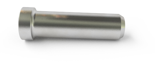
Armature
Steel movable core of the solenoid, used to drive the moving contact assembly.
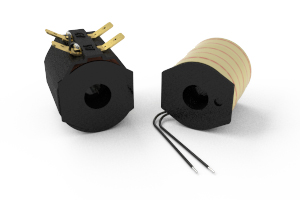
Armature Cap
This is a cap to cover the exposed coil end of the contactor which provides protection against contamination. SW180 and SW200 comes with end caps fitted as standard, SW80 series can be fitted as optional extra. An armature cap is not necessary for ‘P’ types and is not applicable to busbar contactors.
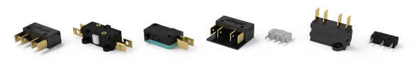
Auxiliary Contacts ('A'/'C')
Single pole double throw auxiliary contacts, used for low power circuit, can be utilised on the majority of our contactors. See the product catalogue for ratings.
B
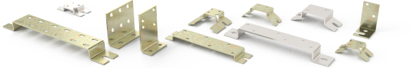
Brackets
A variety of mounting brackets are available, as seen within the catalogue sheets and website product page. Generally these are split into a ‘Top hat’ style for mounting parallel to the mounting surface or an ‘L’ shape mounting bracket for mounting 90 Degrees to the surface.
C
Change Over / Double Throw (DT)
Set of normally open and set of normally closed contactor.
Closed Covers
The aperture usually found in the top cover housing is sealed to form a barrier to assist prevention of airborne contamination into the contact area.
Coil Connection
Coil connection is typically via 6.3mm faston spade terminals. Coil terminals are not polarity sensitive unless suppression is fitted, and the coil is marked accordingly. Flying leads, M5 studs, 4.8mm faston, JPT and other connection methods are available dependant on contactor type.
Coil Finish
Vacuum impregnated coils are available to safeguard against shock and vibration and / or high humidity.
Coil Suppression
See suppression
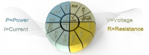
Current (A or I)
Unit = Amp or Ampere. An Ampere is the amount of electrons flowing past a given point in the conductor in one second.
D
Double Pole (DP)
Contact configuration – two sets of single pole contacts
Dropout Voltage
The voltage (V) required to open the contacts (on a normally open contactor) at 20 degree Celsius.
Dust Shields
The aperture usually found in the top cover housing is sealed to form a barrier to assist prevention of airborne contamination into the contact area.
Duty
An explanation on the terminology used to describe the coil ratings is detailed below:
Very Intermittent (HO) – Up to 25% duty Cycle, up to 3 minutes continuous energisation. Highest power in coil allowing strongest return spring to be used, giving optimum switching characteristics.
Intermittent (INT) – Up to 70% duty cycle, up to 15 minutes continuous energisation. High power in coil allowing strong return spring to be used, giving good switching characteristics.
Prolonged (PO) – Up to 90% duty cycle, up to 54 minutes continuous energisation. More powerful than continuous, weaker than intermittent equivalent. Return spring is stronger than continuous but weaker than intermittent.
Continuous (CO) – 100% duty cycle. Continuous operation. Weakest power coil dictating that a weaker, when compared to the intermittent equivalent, return spring is used. This does not give the best switching characteristics for applications switching frequently on load.
Duty Cycle
The on period over the total cycle, supplied as a percentage.
duty cycle = D
t = on time (coil energised)

T = Total cycle time (on time + off time)
where
D is the so-called duty cycle;
t is the duration that the function is non-zero;
Τ is the period of the function.
E
Economy Circuit 'E'
Placed in series with the coil via auxiliary contacts, the economy circuit allows for a very strong initial energisation then provides power consumption on the coil. This allows a strong return spring/coil to be utilised, and thus provides the best switching characteristics.
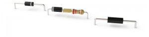
Economy Resistors
Placed in series with the coil via auxiliary contacts, the resistors allow a very strong initial energisation. This allows a strong return spring / coil combination to be utilised, and thus providing the best switching characteristics.
EE Types
Meeting the requirements of UL583 for Type EE Trucks, these contactors are fitted with steel shrouds which create enclosures around the contact housing area. Note these are designed for EE environments and not EX hazardous locations.
EMF
Electro Magnetic Force – this is the transient voltage from the coil when it is switched off.
End Cap
See Armature Cap.
Environmental
Albright operate a ISO 14001:2015 Environmental Management System – Certificate Number: 54527
F
Fixed Contacts
The non movable main contacts. Supplied as bussbar, stud or female thread termination – dependant on model type selected.
Flame Retardant Materials
UL recognised material means good resistance against flammability. Plastics used are generally UL94-V0 and used to help extinguish materials should they ignite.
Flying Leads
Custom colours and lengths of coil terminations can be provided.
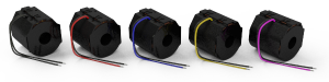
Flying Leads can be terminated with a variety of finishes including;
- Plug
- Wire
- Ring Terminal
Frequency of Switching
How many times does the coil get energised e.g. 2 times a day, twice an hour.
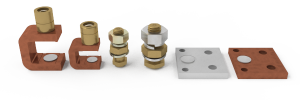
Fuse Holder
Optional to the SD range, the fuse holder is for fitment of an inline fuse direct to the fixed contact, suitable for 51mm and 62mm mounting centres.
J
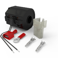
JPT Connector - Junior Power/Timer Connector
This is a 2 pin plug and socket connector type widely used in the automotive sector. It is commonly referenced as a JPT Connector and Albright provide an integrated coil plug that is directly compatible with its socket counterpart – TE Connectivity part number 282189 – please find more information here
L
Large Tips
Whilst not adding to the thermal characteristics of the contactor, large tips offer significantly more contact material than the standard tip and subsequently benefit in supplying greater contact life. Inductive loads, frequent switching and such like will dictate the use of large contacts, due to the nature of contact wear.
Lockable 'L'
Lockable versions of both the ED and SD types are available. For these versions a key is necessary for the knob to be moved from the “Off” position to the “On” position. Once in the “On” position, the key can be removed. Thereafter, the knob may be depressed to the “Off” position where it will automatically lock and remain locked until the key is used again to unlock it. The suffix ‘L’ in this circumstance denotes Lockable.
M
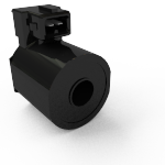
Magnet Frame
Steel enclosure housing the coil (solenoid), armature and other ‘coil assembly’ components.
Magnetic Blowouts
Used to assist breaking of arcs associated with high voltage. Recommended for applications of 48v (inductive) / 60v (resistive) and over. Fitted within the top cover, there is no increase on the overall dimensions.
NOTE: Generally, contacts become polarity sensitive when magnetic blowouts are fitted.
Magnetic Blowouts - High Powered
High power magnets with greater Gauss allows for increased power loads, especially high Voltages. Offered as an optional extra. Fitted within the top cover, there is no increase on the overall dimensions
NOTE: Generally, contacts become polarity sensitive when magnetic blowouts are fitted.
Magnetic Latching
Contact position is secured with the use of a permanent magnet within the coil assembly. The coil requires a pulse(~500ms) to close the contacts, and a reverse polarity pulse (~500ms) to operate the armature and open the contacts, but otherwise remains in the last energised state without the need for power. It should be noted therefore these are not failsafe.
Main Contact
Made of fixed (stationary) and moving contacts – designed to carry the power circuit. Termination may be stud, female or bussbar depending on the contactor type and therefore dictated by requirements and type of application.
Motor Reversing
Configuration for motor reversing, links supplied – will reverse the armature relative to the motor fields.
Mounting Orientation
Normally Open and Changeover – Mounted vertical or horizontal.
When vertical, main contacts mounted above coil assembly.
Normally Closed – Mounted vertical or horizontal.
When vertical, main contacts mounted below coil assembly.
Moving Contact Assembly
The movable main contacts – movement provides the making and breaking of the main contacts.
N
Normally Closed (NC)
Contacts are closed when coil is de-energised.
Normally Open (NO)
Contacts are open when coil is de-energised.
O
Opening on Load
If the contacts are breaking load, hot switching, then the contactor can be considered as opening on load.
Operation
See coil duty.
P
Power
[P or W] Unit = Watt. W=(VxV)/R
Coil power dissipation can be found on the appropriate catalogue sheets, some typical figures are as follows:
| Series | Continuous | Prolonged | Intermittent | Very Intermittent |
|---|---|---|---|---|
| SW60 | 5-7W | 7-10W | 10-14W | >14W |
| SW80 | 7-13W | 13-15W | 15-20W | >20W |
| SW180 | 10-15W | 16-29W | 30-40W | >40W |
| SW200 | 13-21W | 21-30W | 30-60W | >60W |
| SW1000 | 25-31W | 31-40W | 40-75W | >75W |
Protected
Some of our series of contactors are available as protected variants, IP66 or IP67 rated.
Pull-In Voltage
The voltage (V) required to close the contacts (on a normally open contactor) at 20 degree Celsius.
Q
Quality
Our customers expect high standards of product and Albright has set the standard for high quality of contactors, something others are trying to emulate. We operate ISO9001:2015 procedures and actively operate a continual improvement ethos.
R
Rectifier Board
As our coils are wound for D.C., a rectifier can be fitted for A.C. applications.
Resistance
The coil resistance (Ohms) will vary dependant on the ambient temperature and coil temperature. Data provided is at 20 Degree Celsius.
RoHS
Contactors and switches supplied are RoHS compliant.

S
Silver Plating
Our Busbar range of contactors are plated as standard. Silver plating provides an optimum electrical conductor interface between the contactor and the application, and allows heat to be distributed more efficiently. Plating may be excluded at the customer’s option but the effect of temperature rise within the application should be considered.
Single Pole
Contact Configuration – One set of contacts
Super Magnets
Suppression
Diode or diode and series resistors are used to pre-determine the Transient Voltage to an acceptable level; however adding a diode will increase drop out time, adding a resistor will reduce the drop out time but increase the transient voltage.
T
Technical
Albright manufacture their own original designs, and are continually evolving their products in view of cost reduction and new market opportunities. Technical assistance is available, either directly or via the appointed local distributor.
Electrical testing is performed in house, and used to validate new and existing designs.
Temperature
The typical ambient temperature that the contactors can be operated within is from -40 degrees C to +60 degrees C in a 90% non condensing humidity.
The expected coil temperature rise will be approximately up to +70 degrees C. This statement applies to all non magnetic latching Albright contactors, magnetically latching contactors have minimal temperature rise due to the extreme short energisation.
For storage: Albright typically states that the contactors can be stored up to +80 degrees C in a dry/clean environment.
Termination
A variety of coil terminations are available for the majority of our contactor, 6.3mm faston , M5 stud termination and flying leads are amongst more common.
Textured Tips
Used in non switching application. Not essential in applications where main contacts are not being monitored via a sensing signal supplying low current <5A
Top Cover Assembly
Phenolic plastic moulding housing, fixed contacts and in some variants additional components
U
Underwriters Laboratories
In 1986 we started UL testing of products. The Majority of materials are UL 94 V0 recognised.
Our products are recognised under files;
AU2378 – Industrial Electric Vehicles (inductive)
100 cycles 100% endurance load,
50 cycles 150% overload.
E165921 – Power Distribution (resistive)
1000 cycles endurance, 50 cycles 150% overload.
E181430 – Industrial Switches (ED’s)
100 cycles 100% endurance load,
50 cycles 150% overload.
V
Vacuum Impregnated Coils
Prevention against Shock, Vibration and high humidity.
Vibration
Many of our contactors are tested for shock and vibration – the standard tested to is BS EN 61373
Voltage (Electromotive Force)
(V or E) Unit = Volt
Amount supplied across the coil or main contacts, this is not necessarily the system voltage due to voltage drop in the circuit.
W
Washable 'W'
The PC60A-W, PC61A-W and PC63A-W are PC series contactors designed to go through the flux washing processes used in modern PCB production. The auxiliary contacts are supplied separately and the contactors auxiliary actuator hole is temporarily sealed with a rubber plug. After washing the plug can be removed and the auxiliary contact is easily and quickly installed. The PC range fitted with auxiliary contacts cannot be supplied as a Protected (P) Variant.
Windings
We offer coil windings suitable for 6-240v applications.
All coils are wound DC, so if used on AC supplies then a rectifier is required.